Choosing Relays in Practice: What the Datasheet Really Tells You
Relays may be small components in industrial automation, but their impact on overall system reliability is surprisingly large. Can a relay that looks perfectly ordinary be the reason why a production line stops or faults keep recurring? At first glance, many relays seem identical — one or two contact sets, a 24 VDC or 230 VAC coil, … Let’s take a closer look.
In practice, these differences are anything but trivial. The real value of a relay shows up in its reliability — something you only uncover once you start digging into the datasheets. That’s where you’ll find information about contact durability, permissible loads, and expected service life. Unfortunately, these parameters are often skimmed over or ignored altogether. And yet, they are exactly what determines how consistently — and how long — a relay will perform in real-world operation. In the following sections, we’ll take a closer look at what relay datasheets actually say about reliability and how to compare those numbers in a meaningful way.
Three common relays as an example
To keep things from getting too theoretical, we chose three very common relays in Estonia — devices that many automation engineers and electricians have encountered in real installations:
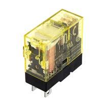
- Idec RJ1S-CL-D24
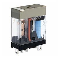
- Omron G2R-1-S 24VDC (S) E
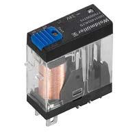
- Weidmüller DRI314024LTD
At first glance, these relays are almost indistinguishable. All three use a 24 VDC coil, have a single changeover contact (SPDT), and feature classic “blade”-type terminals. These are exactly the kinds of components that often get swapped one-for-one in the field, under the assumption that “a relay is a relay.”
In reality, the differences only start to show once you look a bit deeper into the datasheets. That’s why the comparison below is based strictly on official manufacturer specifications:
What exactly are we comparing?
We focused on parameters that have the biggest real-world impact on relay lifetime and reliability. These numbers aren’t just “nice to have” in a table — they determine whether a relay will run reliably for years, or start causing trouble after just a few months.
| Parameter | Omron G2R-1-S 24VDC (S) (E) | IDEC RJ1S-CL-D24 | Weidmüller DRI314024LTD |
|---|---|---|---|
 |
 |
 |
|
| Contact configuration | SPDT (1 Form C) | SPDT (1 Form C) | SPDT (1 CO) |
| Contact material | AgSnIn / Ag alloy | AgNi (silver–nickel) | AgSnO |
| Resistive load AC | 10 A @ 250 VAC | 12 A @ 250 VAC | 10 A @ 250 VAC |
| Resistive load DC | 10 A @ 30 VDC | ≈12 A @ 30 VDC | 10 A @ 30 VDC |
| Inductive load AC | 7.5 A @ 250 VAC (cosφ ≈ 0.4) | 7.5 A @ 250 VAC (cosφ ≈ 0.3) | ≈8 A @ 250 VAC (cosφ ≈ 0.4)* |
| Derived inductive load AC** | 7.5 A @ 250 VAC (cosφ ≈ 0.4) | 10.0 A @ 250 VAC (cosφ ≈ 0.4)** | ≈8 A @ 250 VAC (cosφ ≈ 0.4)* |
| Inductive load DC | ≈5 A @ 30 VDC (L/R ≈ 7 ms) | ≈6 A @ 30 VDC (L/R ≈ 7 ms) | ≈7 A @ 30 VDC (L/R ≈ 7 ms)* |
| Electrical life (rated load) | ≈100,000 operations | ≈200,000 operations | ≈100,000 operations* |
| Mechanical life | 10–20 million | 30–50 million | ≈10 million |
| Max. contact voltage | 440 VAC / 125 VDC | 250 VAC / 125 VDC | 250 VAC / 250 VDC |
| Additional features | plug-in design, indicator variants | LED indicator | LED + test button |
* Data is not explicitly presented as a table by the manufacturer and has been approximately derived from datasheet graphs.
** When normalizing all values to cosφ = 0.4: I ≈ 7.5 × (0.4 / 0.3) = 10.0 A
The most common contact materials in practice
Once you start digging into the inner life of relays, contactors, or other switching devices, you very quickly arrive at a key question: what are the contacts actually made of — and why does that matter at all? In practice, the contact material largely determines how long a device lasts, how well it handles arcing, and whether the contacts tend to weld together over time.
Below are the three most commonly encountered contact materials in industrial applications.
AgSnO (silver–tin oxide)
This is essentially the industrial standard today for inductive loads. AgSnO’s biggest strength is its excellent arc-quenching capability and very high resistance to contact welding. If motors, solenoids, or contactor coils are involved, there’s a good chance AgSnO is doing the heavy lifting. This material is designed to survive “ugly” switching conditions, where arcs are strong, persistent, and unforgiving.
Contact resistance stability with AgSnO is rated slightly lower than with AgNi — not because it’s a poor material, but because of how it behaves during operation. Tin oxide particles embedded in the silver matrix significantly improve arc and welding resistance, but they also mean that the contact surface is never perfectly uniform on a microscopic level. Over time — especially with small currents and infrequent switching — contact resistance may fluctuate a bit more than with AgNi.
AgNi (silver–nickel)
AgNi is the classic “golden middle ground.” It is mechanically robust, offers very stable contact resistance, and is well suited for applications with frequent switching but less aggressive loads. If long service life and consistent behavior are the priority, AgNi is a very safe choice.
AgNi earns top marks for contact resistance stability primarily thanks to its uniform and homogeneous microstructure. Unlike oxide-reinforced materials (such as AgSnO), AgNi contains no insulating particles that could alter the electrical properties of the contact surface over time. Nickel dissolves evenly into the silver matrix, giving the contact good mechanical strength without compromising electrical conductivity.
In practice, this means the contact surface “self-cleans” evenly with every operation, and wear occurs in a predictable and gradual way. Even with low currents and frequent switching, contact resistance remains very stable throughout the relay’s service life. That’s why AgNi is often used in applications where arc handling is less critical than precise, repeatable, and reliable contact behavior.
AgSnIn and other silver alloys
These materials are typically found in more general-purpose applications. Welding resistance and stability are perfectly adequate, but under very strong arcing conditions they clearly fall behind AgSnO and AgNi. In other words: they get the job done, but there are better options for extreme environments.
The reason AgSnIn and other silver alloys are still widely used is not because they represent “top-tier” performance, but because of the balance between properties, cost, and application requirements. In many devices, there are no strong arcs, large inductive kickbacks, or extreme switching frequencies. In such cases, using AgSnO or AgNi would be technically possible — but often unnecessarily expensive or simply overkill.
Here’s a quick summary table:
| Contact material | Arc tolerance | Welding resistance | Contact resistance stability | Typical use |
|---|---|---|---|---|
| AgSnO | ⭐⭐⭐⭐☆ | ⭐⭐⭐⭐⭐ | ⭐⭐⭐⭐☆ | Inductive loads, motors, solenoids |
| AgNi | ⭐⭐⭐⭐☆ | ⭐⭐⭐⭐☆ | ⭐⭐⭐⭐⭐ | Frequent switching, moderate loads |
| AgSnIn / Ag alloys | ⭐⭐⭐☆☆ | ⭐⭐⭐⭐☆ | ⭐⭐⭐⭐☆ | General-purpose applications |
What may seem like a small detail at first glance — the choice of contact material — is in reality one of the most important decisions when it comes to the reliability of the entire switching circuit.
Load type – resistive or inductive
One of the most critical factors in relay reliability is what kind of load the contacts are actually switching. Datasheets usually include this information, but in real-world projects the load type often gets overlooked.
Resistive load
With resistive loads, electrical energy is mainly converted into heat. Typical examples include:
- heating elements
- resistors
- incandescent lamps
Switching these loads is relatively “easy” for relay contacts — current and voltage are generally stable, and arc formation is short-lived.
Inductive load
With inductive loads, energy is stored in a magnetic or electric field and then released back into the system during switching. This category includes:
- contactor coils
- solenoids
- relay coils
- motors and transformers
Inductive loads are where the real trouble starts. This is where you see:
- large inrush currents
- high voltage spikes during switch-off
- strong and persistent arcing at the contacts
Why is this especially important in industrial automation?
Most loads switched by relays in industrial automation are not resistive loads, but inductive loads. The most common examples are contactor coils and solenoids, which are often switched frequently and over long periods of time.
This means relay contacts spend much of their life operating under conditions that are significantly harsher than what the nominal current rating alone might suggest. If the load type is ignored, a relay’s real-world lifetime can easily be reduced by a factor of several.
This is exactly where the real differences between relays, contact materials, and manufacturers begin to show.
Inductive AC load – letting the numbers speak
Let’s now move on to concrete numbers and take a closer look at the rows in the table that deal with inductive loads on AC networks. At first glance, the values look quite similar, and nothing immediately jumps out.
| Parameter | Omron G2R-1-S 24VDC (S) E | Idec RJ1S-CL-D24 | Weidmüller DRI314024LTD |
|---|---|---|---|
| Inductive load AC | 7.5 A @ 250 VAC (cosφ ≈ 0.4) | 7.5 A @ 250 VAC (cosφ ≈ 0.3) | ≈8 A @ 250 VAC (cosφ ≈ 0.4)* |
| Derived inductive load AC** | 7.5 A @ 250 VAC (cosφ ≈ 0.4) | 10.0 A @ 250 VAC (cosφ ≈ 0.4)** | ≈8 A @ 250 VAC (cosφ ≈ 0.4)* |
Values marked with an asterisk (*) are taken from graphs in the manufacturer’s datasheets and are not presented directly in tabular form. Double asterisks (**) indicate values that have been normalized to the same cosφ so the figures can be compared on an equal basis.
This last step is crucial. Once the values are brought to the same cosφ, the picture starts to become much clearer, and the Idec relay clearly stands out with a higher tolerance for inductive loads. This may not be obvious at first glance, but it becomes very apparent when you dig a little deeper into the datasheets.
What does this mean in real life?
For contactor coils, the cosφ during steady-state operation is typically around 0.3. At the moment of energizing, cosφ can rise to approximately 0.75, but at the same time the current increases very sharply. In practice, inrush currents can be up to ten times higher than the nominal current.
Of course, a contactor with a 7.5 A coil is relatively large and uncommon in industrial automation. In the context of relay comparison, however, this does not mean that such a coil will actually be switched. Instead, it reflects the relay’s switching robustness — how solid the contact design is and how well the relay can cope with harsh, inductive conditions.
DC inductive load and electrical lifetime – where the real differences emerge
With AC loads, the current zero-crossing helps the relay contacts. With a DC inductive load, that luxury simply does not exist. This is exactly where relay design, contact material, and arc resistance start to matter the most.
Let’s look at two rows in the table that are particularly telling in real-world applications.
| Parameter | Omron G2R-1-S 24VDC (S) E | Idec RJ1S-CL-D24 | Weidmüller DRI314024LTD |
|---|---|---|---|
| DC inductive load | ≈5 A @ 30 VDC (L/R ≈ 7 ms) | ≈6 A @ 30 VDC (L/R ≈ 7 ms) | ≈7 A @ 30 VDC (L/R ≈ 7 ms)* |
| Electrical lifetime (at rated load) | ≈100,000 operations | ≈200,000 operations | ≈100,000 operations* |
Values marked with an asterisk (*) are not provided directly in table form by the manufacturer and have been derived from datasheet graphs.
For DC inductive loads, the key factor is the L/R ratio, which describes how long the inductive load retains energy after switch-off. A value of L/R ≈ 7 ms is very typical in industrial automation and closely matches the behavior of solenoids and smaller contactor coils.
An interesting observation here is that although Weidmüller appears to allow the highest DC current, this does not directly translate into a longer electrical lifetime. Idec stands out in terms of the number of switching operations permitted at rated load, which points to excellent resistance of the contacts to DC arcing.
In practice, this means that for DC inductive loads, it is not enough to look only at the maximum current rating. Equally important is how many times the relay can actually switch that load before the contacts begin to degrade noticeably.
Electrical vs. mechanical lifetime – why big numbers can be misleading
Let’s take a closer look at two rows that often cause the most confusion when reading relay datasheets.
| Parameter | Omron G2R-1-S 24VDC (S) E | Idec RJ1S-CL-D24 | Weidmüller DRI314024LTD |
|---|---|---|---|
| Electrical lifetime (at rated load) | ≈100,000 operations | ≈200,000 operations | ≈100,000 operations* |
| Mechanical lifetime | 10–20 million | 30–50 million | ≈10 million |
At first glance, it’s the mechanical lifetime figures that grab your attention. Tens of millions of operations can easily give the impression that the relay will last forever. In reality, this number means something quite different from what many assume.
Mechanical lifetime refers to contact movement without any electrical load. The contacts open and close, springs do their job, but no arc is formed and the contact surfaces do not wear. It is a good indicator of mechanical quality, but it does not directly describe reliability in real applications.
In industrial automation, the actual service life of a relay is almost always determined by its electrical lifetime. It is under rated load that arcing, heating, and contact erosion occur — and this is where the numbers drop from millions to hundreds of thousands.
At this point, a small practical calculation helps put things into perspective. If a relay has an electrical lifetime of 100,000 switching operations and it switches a full load every 5 minutes, this results in 288 operations per day. At this rate, the specified switching limit is reached in about 347 days — just under a year. In other words, even with a fairly moderate switching frequency, the electrical lifetime is not an abstract number, but a very real and tangible limit.
Interestingly, in the case of the Idec relay, the higher mechanical lifetime aligns with a better electrical lifetime as well. This suggests a well-balanced design, where mechanical robustness and contact durability support each other.
In practice, when selecting a relay, it’s worth asking one simple but crucial question:
How many times can this relay realistically switch my load?
Mechanical lifetime may look impressive on a datasheet, but from a reliability standpoint, it is mostly background information.
Conclusion – a small relay with a big impact
A relay is a small and inexpensive component in industrial automation — typically just three to six euros — yet its failure can cause major downtime and frustrating faults.
Relays that look identical are not necessarily equivalent: contact material, arc resistance, and switching capability are what ultimately determine reliability.
That’s why a relay is not the place to cut corners. The right choice ensures your production line runs smoothly and reliably — saving a few euros up front can end up costing many times more down the line.
Explore our relay selection: Relays – Information & Sales | Electrobit OÜ