The truth about frequency converters: how to recognise a reliable device and when to be cautious
When searching online for information on how to choose a frequency converter, the focus is usually on motor power, rated current, voltage and application. All of these are, of course, important parameters. However, surprisingly little is said about how to assess the actual reliability of a frequency converter. So let’s take a look inside the frequency converter.
With tools, things are simpler. We have all seen pliers or screwdrivers made of soft metal – at first they seem usable, but they do not last long. And then there are tools made of high-quality steel that last for years. The difference is easy to feel.
But what about frequency converters? What signs indicate whether a device is truly reliable, or one that already raises doubts before installation?
What does reliability mean in the context of a frequency converter?
How should the reliability of a frequency converter be assessed? Simplified, it can be reduced to two main aspects: resistance to time and resistance to extreme situations.
In other words – will the device operate reliably for years under normal conditions, and will it survive those moments when things do not go according to plan, such as short-term overloads or unexpected operating modes?
It is often said that what moves, wears out. In power electronics, however, almost nothing moves – except the cooling fan. But this does not mean that no wear occurs. A frequency converter contains several key components whose ageing directly determines the lifetime of the entire device.
So what actually wears out?
Memory and control electronics
Microprocessors and memory chips, especially certain types such as flash memory, have a limited number of write cycles. This is usually not the first component to fail in a frequency converter, but in cheaper devices frequent parameter saving or poor memory management can cause issues over time.
Capacitors
Capacitors are classic wear components in power electronics. Electrolytic capacitors in particular age due to time and temperature, as well as repeated charge and discharge cycles. The higher the operating temperature, the faster their parameters degrade. This makes capacitor quality and cooling critically important for the reliability of a frequency converter.
IGBT modules (isolated gate bipolar transistors, in English Insulated Gate Bipolar Transistors)
The most important components in a frequency converter are the IGBT modules that switch the motor current. Every overload places additional stress on these components. A single overload may not cause immediate failure, but repeated overloads lead to internal semiconductor fatigue and reduced service life. This is why the selection margin of the IGBTs and the effectiveness of overload protection play a decisive role.
Reliability before purchase: what can and cannot be assessed
In practice, no one dismantles a frequency converter before buying it to check which memory chip is used, which brand of capacitors are installed, or which exact IGBT module has been selected. And honestly, they should not have to.
This leads to a logical question: how can the reliability of a frequency converter be assessed before it has been in operation?
Unfortunately, the quality of memory chips and capacitors is very difficult to evaluate without looking inside the device. These aspects depend largely on the manufacturer’s integrity and engineering discipline.
However, there is one component whose reliability can be assessed through indirect but fairly reliable indicators – the selection of the IGBT modules. This is where manufacturers often make either conservative or borderline design choices, and these decisions are directly reflected in allowable loads, safety margins, and long-term durability.
The reason is simple: IGBT modules are among the most expensive components in a frequency converter. To “optimize” product cost, compromises are often made specifically in IGBT selection – using devices with lower current margins or more restrictive operating conditions. On paper, the converter may still meet its nominal ratings, but real-world reliability suffers due to the reduced margin.
Fortunately, there are several signs that allow these compromises to be identified even before purchase. In practice, three indicators stand out most clearly.
First, the cooling method of the frequency converter. If IGBT margins are small, the manufacturer must strictly control their temperature, which places limitations on cooling and ambient conditions.
Second, the permitted motor cable length between the frequency converter and the motor. Long motor cables impose higher electrical stress on IGBTs. A short permitted cable length often indicates limited power-stage margin.
Third, whether disconnecting the frequency converter output during operation is allowed. This situation creates additional electrical stress for the IGBTs. If the manufacturer explicitly prohibits it, this is often a sign of limited design margin in the power stage.
How a frequency converter works – and why the IGBT plays a key role
Let us briefly look at what actually happens inside a frequency converter.
The incoming AC voltage from the mains is first rectified using a diode bridge and stored in capacitors. This creates a DC voltage in the intermediate circuit, which serves as the energy backbone of the system.
Next comes the heart of the frequency converter – the processor and the IGBT modules. Under processor control, the IGBTs switch the DC voltage on and off very rapidly. This is done using pulse width modulation (PWM).
The result is not a perfect sine wave, but a sine-like AC voltage whose amplitude and frequency can be precisely controlled. This voltage is used to power the motor.
By changing the switching frequency and pattern, the frequency converter controls motor speed and torque. This means the IGBT modules must handle high currents, high voltages, and very fast switching speeds – making their quality and margin absolutely critical for reliability.
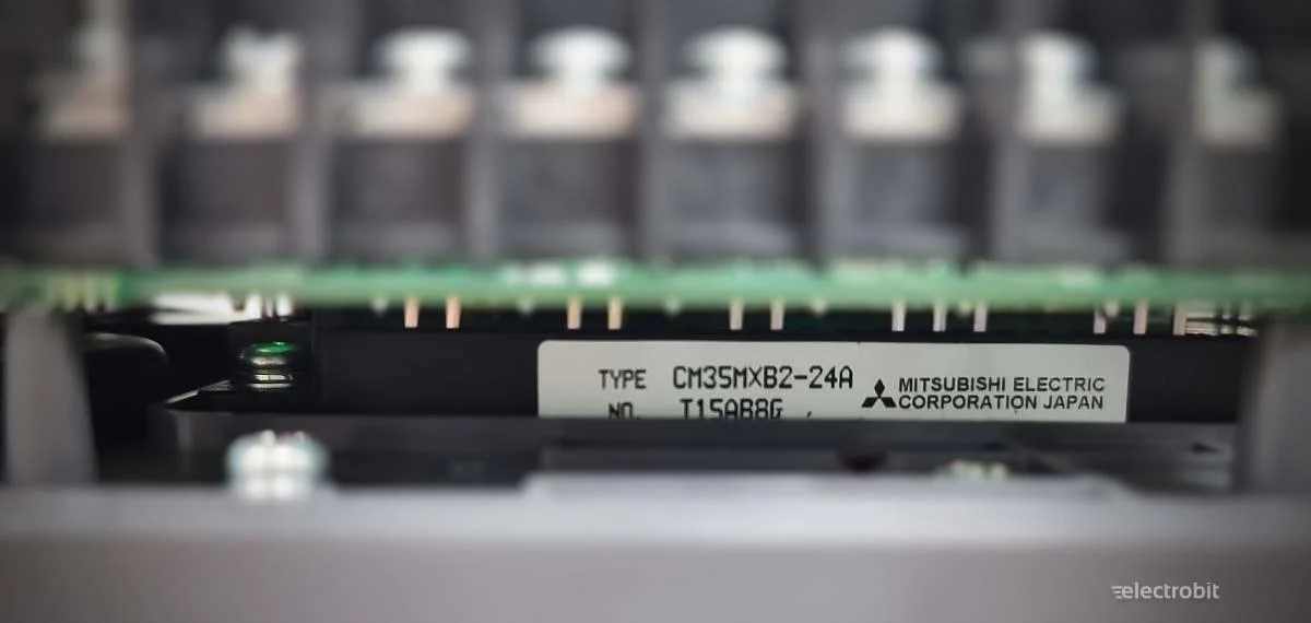
Temperature dependence of IGBT parameters – the Mitsubishi CM35MXB2-24A example
Let us now examine a concrete, real-world example.
Mitsubishi Electric uses the IGBT module CM35MXB2-24A, among others, in the FR-D740-120SC-EC frequency converter. Datasheet: CM35MX-24A
According to the datasheet, the inverter section of this IGBT module has a nominal current of 35 A. However, it is crucial to understand under what conditions this value applies.
Most electrical parameters in the datasheet are specified at a junction temperature (Tj) of 25 °C.
Junction temperature refers to the temperature of the IGBT chip itself, not the ambient air or even the heatsink temperature. It is the internal semiconductor temperature where all heat ultimately accumulates.
The same datasheet specifies a maximum allowable junction temperature of approximately 150 °C.
This does not mean the IGBT can be operated continuously at 150 °C at full nominal current. On the contrary – this is an absolute maximum limit, beyond which the risk of failure increases dramatically.
As junction temperature rises:
- conduction and switching losses increase,
- allowable continuous current decreases,
- internal semiconductor ageing accelerates.
Therefore, the actual permissible operating current is significantly lower as junction temperature approaches its maximum limit. The 35 A nominal current is achievable only if the chip can be kept near 25 °C – a condition rarely achievable in real installations.
In practice, control cabinet temperatures are seldom 25 °C. Industrial environments typically see 35–45 °C, and hot cabinets can exceed this. This raises the IGBT junction temperature and requires current derating.
This is why the CM35MXB2-24A module is used conservatively in the FR-D740-120SC-EC frequency converter:
- nominal output current of 12 A,
- allowable ambient temperature up to +50 °C,
- short-term overload capability of 200% for 0.5 seconds.
This is a textbook example of deliberate derating. The IGBT’s electrical capability is selected with substantial margin to ensure:
- operation at elevated temperatures,
- tolerance of short-term overloads,
- long-term reliability beyond laboratory conditions.
This gap between the IGBT’s theoretical current rating and the frequency converter’s practical nominal current is what distinguishes a reliable drive from one that only works “on paper” but quickly limits or fails in hot cabinets or under load.
Why the cooling method of a frequency converter matters
When discussing cooling, it is often assumed that having a fan is sufficient. In reality, the more important question is what the fan cools and how heat is removed from the device.
Two basic approaches are common. In one, airflow is directed straight onto the IGBT module or a small heatsink. In the other, the IGBT is mounted to a large heatsink, and the fan primarily cools the heatsink.
At first glance, direct cooling may seem superior – air reaches the hottest point immediately. In the short term, this can be true. However, this approach depends heavily on fan performance, airflow cleanliness, and ambient conditions. As fans age, dust accumulates, or ambient temperature rises, IGBT temperature can increase rapidly.
The key difference lies in thermal mass. A small heatsink has very low thermal capacity. Load changes and overloads translate almost instantly into junction temperature swings. These rapid thermal cycles are particularly damaging to semiconductors.
By contrast, a large heatsink provides significant thermal mass, acting as a buffer. Short-term overloads do not immediately raise IGBT temperature, as heat is absorbed by the heatsink. Temperature changes are slower and more uniform.
In practice, this results in lower and more stable operating temperatures. As shown earlier, temperature is critical for semiconductor lifetime. Greater thermal mass and temperature stability directly translate into longer IGBT life and better overload tolerance.
A large heatsink is therefore not merely a construction detail. It is a clear sign that the manufacturer has designed the converter for real-world conditions – hot cabinets, uneven loads, and long service life. Thermal mass is the key factor that separates robust frequency converters from marginal designs.
Cable length and output disconnection – indicators of IGBT margin
Some datasheet parameters may initially appear to be simple installation guidelines. In reality, they directly reflect how much margin the IGBTs have and how well the converter handles extreme conditions.
One such parameter is the permitted motor cable length.
Long motor cables are electrically demanding. They introduce inductance and capacitance that create additional voltage and current spikes during IGBT switching. The longer the cable, the greater these spikes – and each spike represents additional electrical and thermal stress.
If only short cable lengths are allowed, it often indicates that the IGBTs are already operating close to their limits. Longer cables would push them beyond safe margins.
Conversely, converters that allow long motor cables without additional filters typically indicate more conservatively selected IGBTs and cooling, with sufficient electrical and thermal margin.
Another revealing indicator is whether the output may be disconnected during operation, for example using a contactor.
From the IGBT’s perspective, this is one of the most stressful scenarios. Sudden load loss or reconnection generates severe transients. If the converter is not designed for this, damage can occur instantly.
For this reason, many converters strictly prohibit output disconnection during operation – a clear sign of limited margin. Devices that allow it are designed with the assumption that IGBTs, cooling, and thermal mass can withstand such events.
When cooling design, cable length allowance, and output disconnection capability are considered together, the true nature of a frequency converter becomes clear. These are not convenience features – they are reliable, indirect indicators of robustness.
Conclusion – when a frequency converter shows its true character
Today, frequency converters are an integral part of automated processes. They control motors, maintain process stability, and usually operate unnoticed in the background. Under ideal conditions, almost all frequency converters appear “good” – loads are stable, temperatures moderate, and nothing unexpected occurs.
But real life is not ideal.
Mechanical systems can jam, conveyors can be overloaded, pumps may start against closed valves, or debris may enter a fan. In such situations, motor load rises instantly – along with the converter’s output current.
The critical question then becomes:
does the converter fail catastrophically or activate protection?
And even more importantly – how many such overload shocks can it endure before internal components, especially IGBTs, fatigue and fail?
This is where true reliability reveals itself.
Although IGBTs, capacitors, and memory chips are hidden inside the device, manufacturers leave clear traces of their design choices in datasheets and construction. Knowing how to read these signs allows informed decisions even before purchase.
Our recommendation – whether subjective or not – is simple:
Choose a frequency converter with a large heatsink and substantial thermal mass, where the fan primarily cools the heatsink rather than blowing directly onto electronics.
Compare the permitted motor cable length – it reflects the electrical margin of the design. As a rule of thumb, up to about 200 m for small drives (up to ~1.5 kW) and 400–500 m for larger ones is a good sign.
If the datasheet specifies only around 100 m, it is worth pausing to question how much margin the design truly has.
Finally, verify that disconnecting the output during operation (e.g. via a contactor) is explicitly allowed – this is a strong indicator that the converter is designed for real-world conditions.
Summary in one sentence
The hallmarks of a reliable frequency inverter are simple: a large heatsink, a long permitted motor cable length, and clear confirmation from the manufacturer that interrupting the output circuit during operation (e.g. using a contactor) is permitted and does not damage the IGBT modules.
Explore our range of reliable frequency converters: Frequency converters – Information & sales | Electrobit OÜ